Basic Breadboard Synth
August 1, 2026
I stumbled upon a YouTube video called Fun With Transistors by HackMakeMod (link):
In it, he shows how setting up two inverter circuits with inputs chained to the other's outputs, and adding a capacitor in-line with one of the feedbacks will create an oscilator circuit.
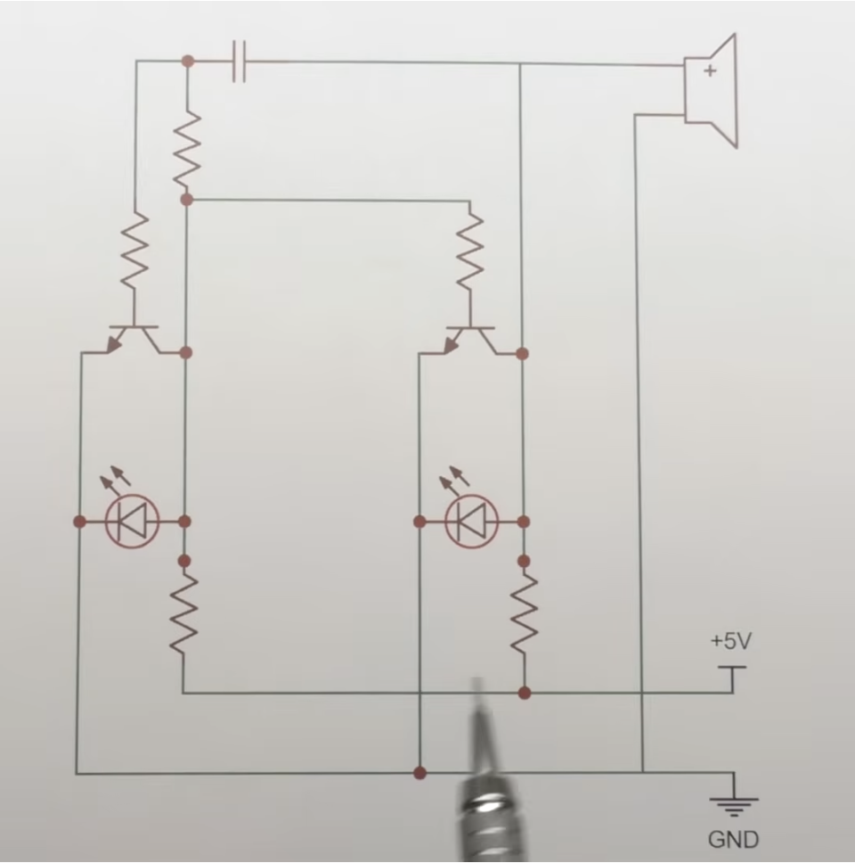
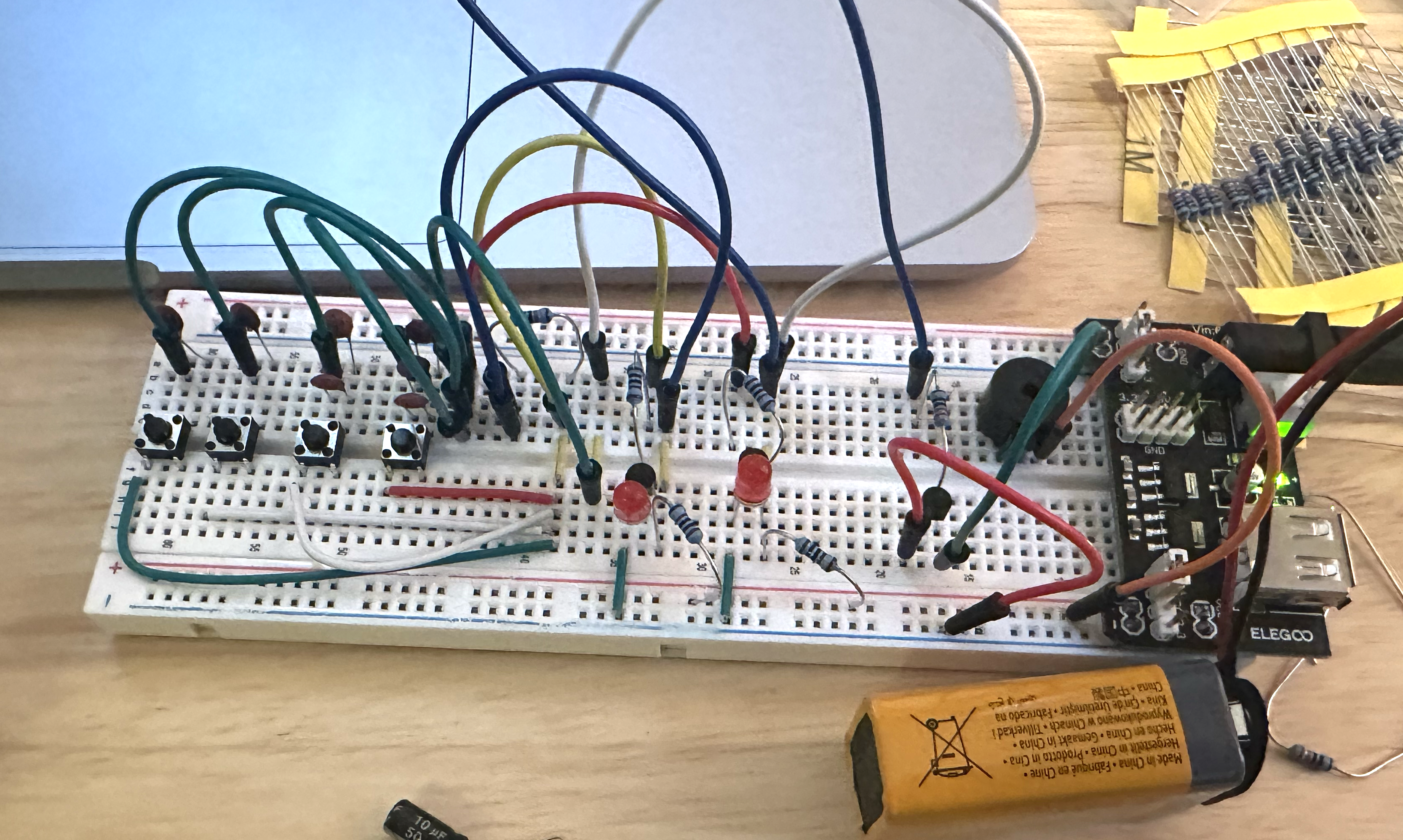
I set up this circuit on my breadboard and added a passive buzzer to the output of one of the inverters. I had to use this output to trigger the gate a third transistor to get enough power to the buzzer to make an audible sound.
This circuit reminded me of way back in undergrad when we learned how to calculate the frequency of a LC circuit. I didn't really remember what an LC circuit was, but I knew that there was a relationship between the size of the capacitor used in the circuit and the frequency.
I set up 4 buttons that could add some combination of 0.1 microfarad capacitors in parallel on the feedback line. Capacitors in parallel increase the total capacitance by summing all the individual capacitances.
Button 1 connected 1 capacitor.
Button 2 connected 1 capacitor.
Button 3 connected 2 capacitors.
Button 4 connected 3 capacitors.
Pushing different combinations of buttons could activate 1-7 capacitors which would play different notes on the buzzer.
(unfinished past here)
Using my piano, I found that the buzzer buzzed at approximately an A flat note in the 4th octave.
2 capacitors were around A flat in the 3rd octave.
3 capacitors were around D flat.
4
5
6
7
The intervals between each additional capacitor were:
- octave, fifth, third, etc
Harmonic series!
This makes sense because the capacitance is
1C, 2C, 3C, 4C, ...
Which means that the multiplier between each is
x2, x3/2, x4/3, x5/4, ...
Or if we reverse the order
x4/5, x3/4, x2/3, x1/2