ESP32 Bluetooth Audio Receiver
July 4, 2026
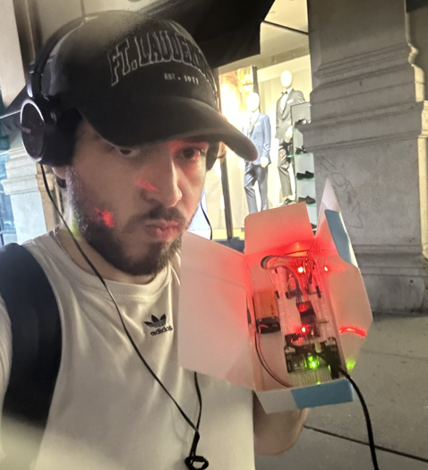
I want to build a DIY low-latency wireless monitoring system for live music performances. At my last concert there were a few songs where I lost sync with the backing track and would have benefited from In-Ear-Monitors.
These systems can get pretty pricey and I thought would be a good DIY electronics project to see if I could recreate the functionality I want without paying for fancy professional gear. After some research I decided to use the ESP32 platform.
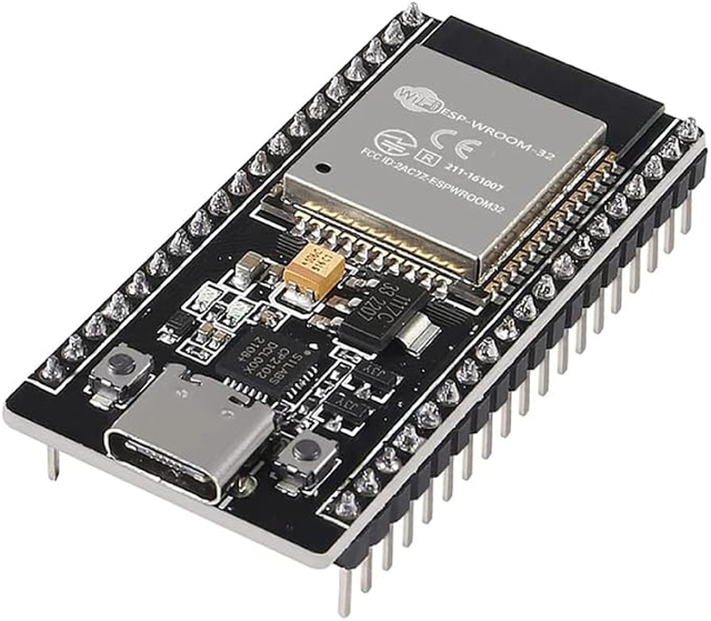
The first thing I wanted to verify was outputting audio from the chip. I found a tutorial (https://www.makerguides.com/playing-audio-with-esp32-and-pcm5102/) for a simple bluetooth receiver. I got a PCM5102 Digital-to-Analog Converter (DAC) board to use provide audio functionality to the ESP32 using the Inter-Integrated-Circuit Sound (I2S) protocol.
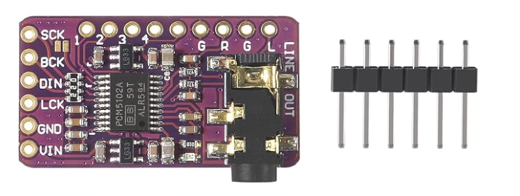
I followed the wiring guide in the tutorial and flashed the sample code. When the device is powered on, it advertises itself as a bluetooth audio device. I was able to connect to it with my phone and play music on the headphones connected to the audio jack on the PCM5102 board.
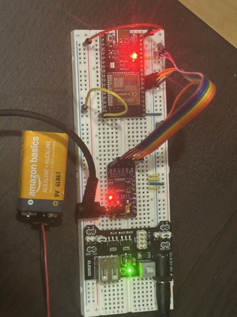
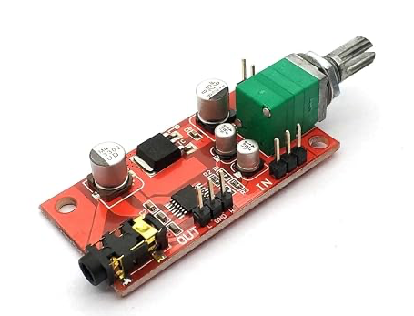
I wasn't sure if this would work because the PCM5102 board only outputs audio at "line level". This means that the signal power is meant for transfering audio from device to device rather than amplifying it on headphones. Typically, an audio output that is driving a set of headphones would be amplified to "headphone level". My headphones still output the sound clearly, but it was a lot quieter than usual. In the next iteration I will connect the output to an amplifier. I ordered the MAX4410 headphone amplifier board and will test with it next time: